

Thermal Air Forcing vs. the TEC Method for Thermal Testing of Fiber Optic Transceivers

The rapid growth of AI and hyperscale data centers is pushing fiber optic technology further than ever before. As optical modules advance from 800G—and now toward 1.6T —they’re moving more data, consuming more power, and generating more heat, all within virtually the same footprint.
For engineers, this has placed greater emphasis on temperature testing, thermal tuning, and thermal cycling during product development. The objective isn’t simply to expose a device to hot and cold temperatures, but to understand how temperature affects performance, reliability, and long-term operation.
There are two common approaches to temperature forcing used for this type of testing: the TEC (thermoelectric cooler) method, a direct-contact temperature forcing approach, and localized thermal air forcing.
Direct-contact systems transfer heat through a temperature-controlled surface that touches the device under test. Thermal air forcing delivers a controlled stream of conditioned air around the device, more closely reproducing the airflow found in many real-world operating environments.
For pluggable optical transceivers used in AI servers and hyperscale data centers, understanding the differences between these two methods helps engineers select the temperature forcing approach that best supports their thermal characterization and validation work.
Temperature Characterization and Thermal Tuning
Temperature characterization is more than exposing a fiber optic transceiver to hot and cold temperatures. It’s a controlled process that helps engineers understand how an optical module performs as its thermal environment changes.
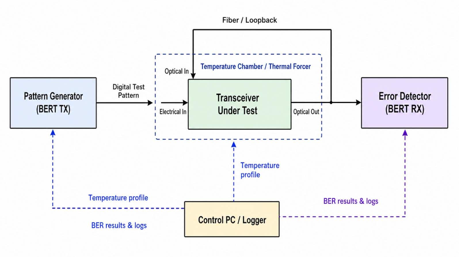
A typical setup combines a temperature forcing system with the customer’s existing test equipment. The temperature forcing system follows a programmed temperature profile, while instruments such as a Bit Error Rate Tester (BERT), power supplies, optical test equipment, and a control PC monitor and record the module’s performance at each temperature step. Together, they build a complete picture of how the device responds throughout its operating range.
During thermal tuning, engineers aren’t simply verifying that the module still works at a particular temperature. They’re looking for changes in performance as the device moves through its operating range. Measurements such as bit error rate (BER), signal integrity, optical power, timing margins, and other operating characteristics can reveal how temperature affects overall performance and reliability.
By repeating this process through multiple temperature setpoints—or during temperature cycling—engineers can identify trends, optimize performance, and better understand how the transceiver is expected to behave before it’s deployed in an AI server or hyperscale data center.
The temperature forcing system doesn’t perform the electrical or optical testing. Its role is to create a stable, repeatable thermal environment so the customer’s test equipment can accurately characterize the device under real operating conditions.
Pluggable Optical Modules Are Designed to Operate in Forced-Air-Cooled Environments
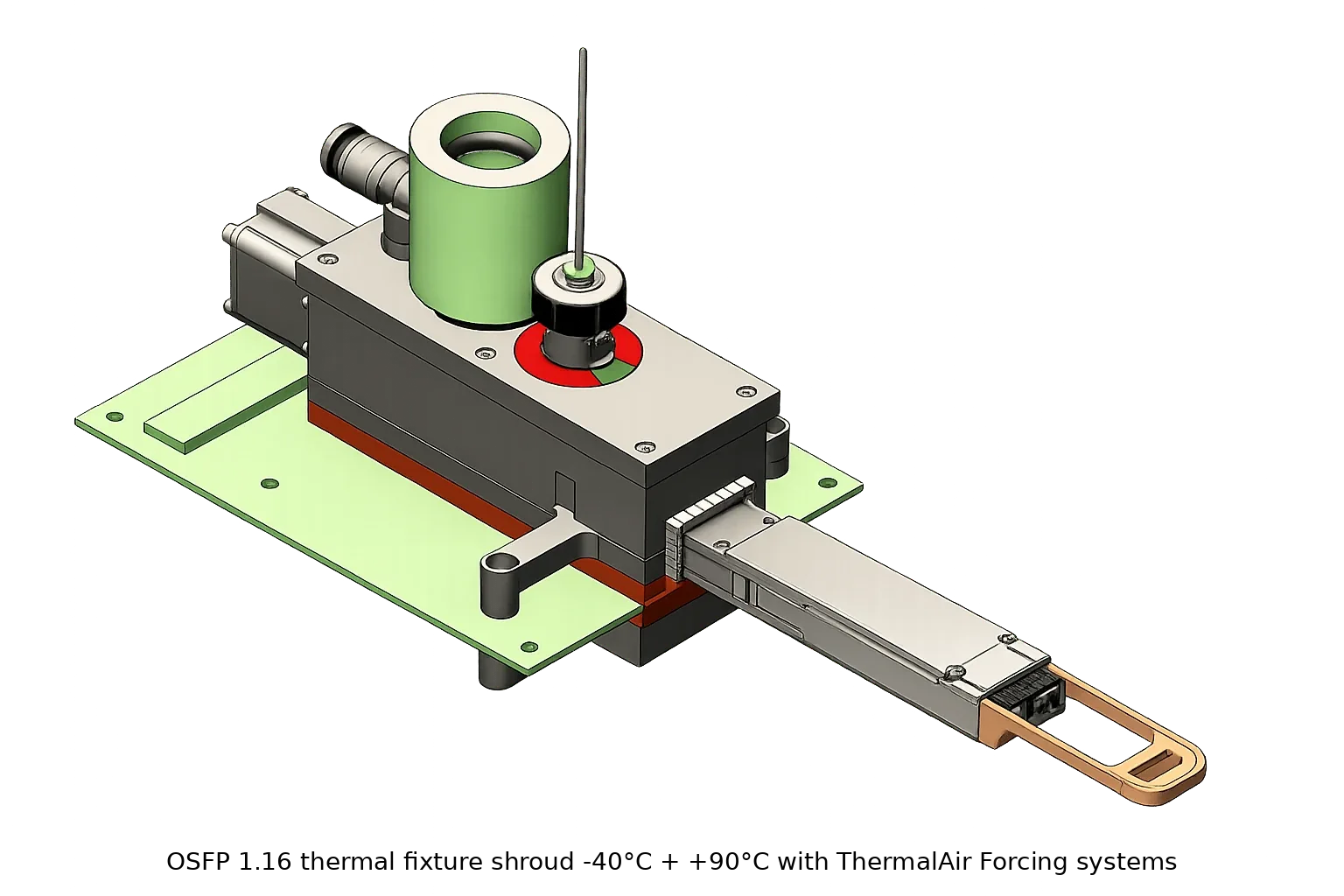
Pluggable optical modules (SFP, SFP+, QSFP, QSFP-DD, OSFP, etc.) are designed to operate in equipment that provides forced-air cooling. The relevant MSAs and system design guidance assume the host equipment—whether it’s a switch, router, or server—provides airflow over the module. The module’s heat sink, cage, and thermal design are intended to work within that airflow. They are not designed to be clamped to a temperature-controlled cold plate during normal operation.
Thermal tuning often focuses on airflow as much as temperature. Engineers aren’t just trying to reach a target setpoint; they’re evaluating how efficiently the module rejects heat while maintaining optical and electrical performance.
As data rates continue to increase, so do power levels. Today’s 400G and 800G optical transceivers can dissipate well over 10 watts, with next-generation 1.6T modules expected to push even higher. In a fully populated switch, dozens of transceivers are competing for the same cooling air. Neighboring modules, fan speed, airflow direction, and chassis design all influence the temperature each module actually sees.
Those are exactly the conditions engineers want to reproduce during temperature testing, thermal tuning, and thermal cycling. The closer the laboratory environment matches the operating environment, the more confidence they can have that the performance measured during testing will carry over into the field.
This is why temperature characterization of fiber optic components is often more accurately achieved using localized thermal air forcing rather than the TEC method. Both technologies have their place in electronics testing, and each offers distinct advantages depending on the application. Let’s take a closer look at each approach.
TEC (Thermoelectric Cooler) Method: Direct-Contact Temperature Forcing
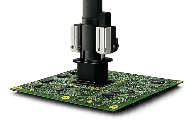
The TEC (thermoelectric cooler) method is a well-established approach for thermal characterization, reliability testing, and production screening of electronic devices. Using a solid-state thermoelectric device in direct thermal contact with the device under test (DUT), heat is transferred into or out of the DUT through a controlled thermal interface rather than by changing the surrounding air temperature. This approach provides precise temperature control, rapid thermal response, and localized heating or cooling where it is required.
The TEC method is widely used for semiconductor devices, processors, GPUs, FPGAs, ASICs, power electronics, and other components that transfer heat through a package, heat spreader, lid, or other mechanical interface. It is also well suited for applications requiring temperature control of a specific device on a populated circuit board while minimizing the thermal impact on neighboring components.
Like thermal air forcing, the TEC method can support temperature characterization, thermal tuning, temperature cycling, and reliability testing. However, repeated hot-to-cold temperature cycling can reduce TEC reliability and shorten service life compared with applications where the device is held at relatively stable temperatures for longer periods. This can be an important consideration in fiber optic transceiver testing, where repeated temperature cycling is often part of characterization and validation. A transceiver also has a finite thermal-cycle life, making repeated cycling an important part of evaluating long-term device reliability. The difference is not that one technology is inherently better than the other, but that each creates a different thermal environment and is suited to different engineering objectives.
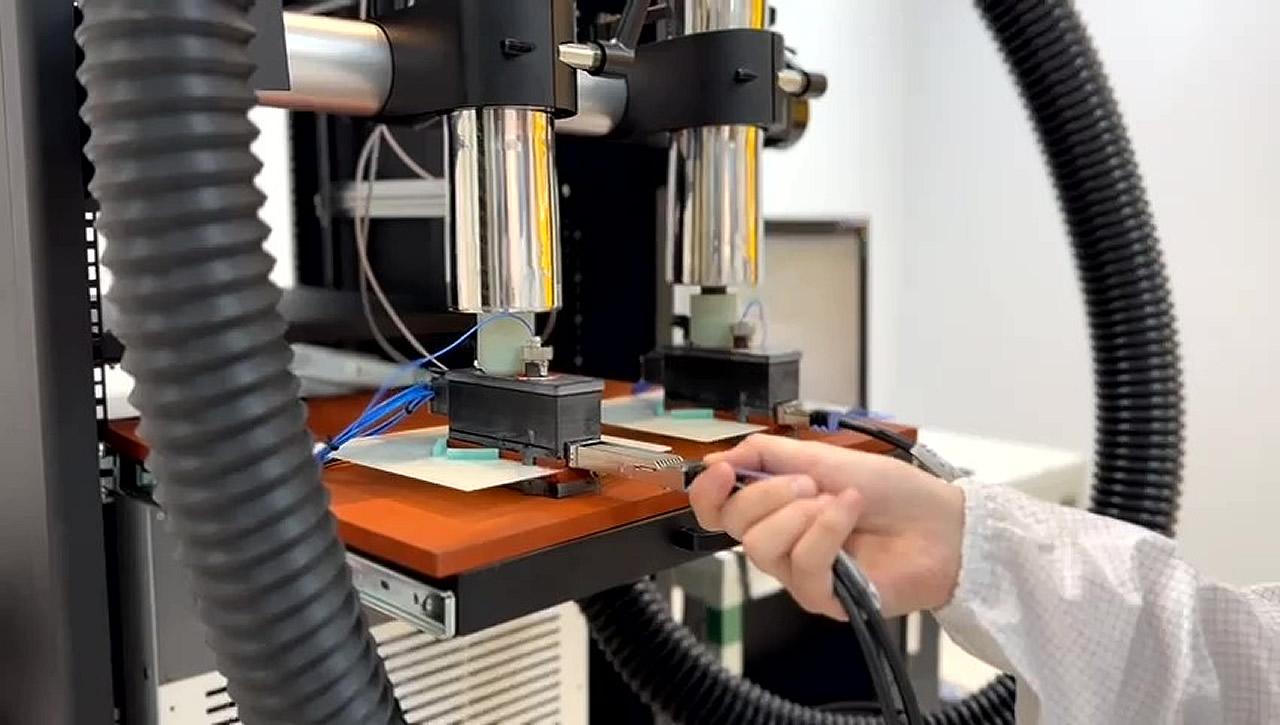
When evaluating semiconductor packages, high-power devices, or conduction-cooled assemblies, the TEC method is often the preferred approach. However, many electronic devices—including fiber optic transceivers—operate in changing environmental air conditions rather than through direct thermal conduction. For these applications, reproducing the device’s intended operating environment can be just as important as achieving the target temperature. In those cases, localized thermal air forcing provides an effective method for environmental temperature characterization, thermal tuning, and temperature cycling.
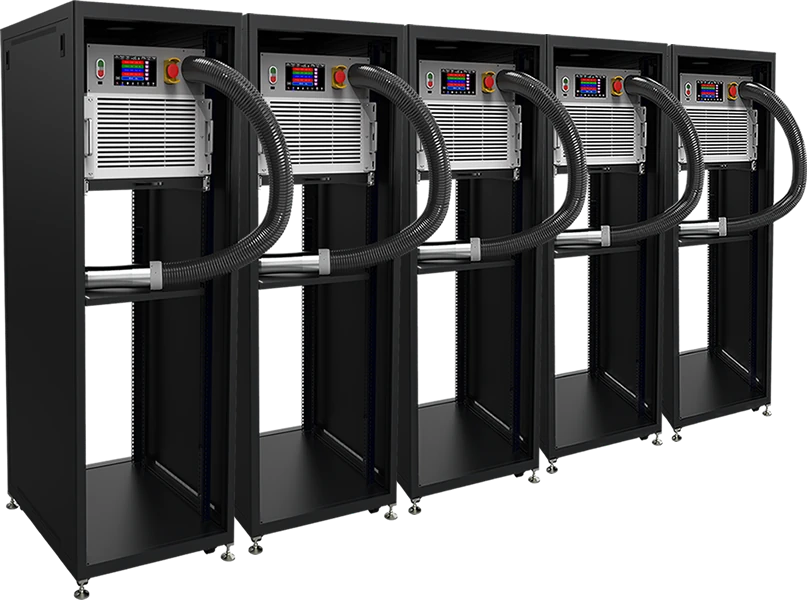
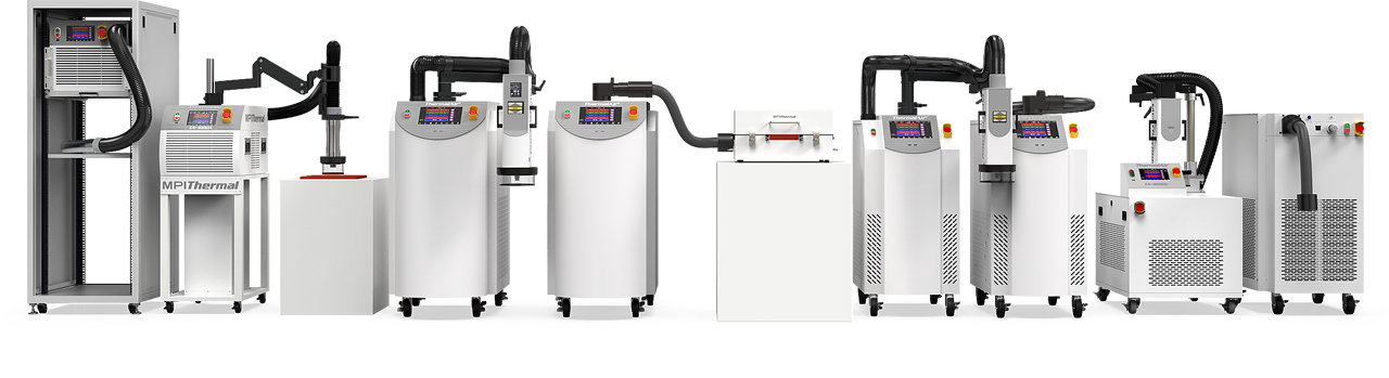
To view the complete product line of MPI Thermal ‘s Temperature Testing Solutions…
-
Thermal Air Forcing vs. the TEC Method for Thermal Testing of Fiber Optic Transceivers
Thermal Air Forcing vs. the TEC Method for Thermal Testing of Fiber Optic Transceivers The rapid growth of AI and hyperscale data centers is pushing...
-
How MPI Thermal Helps Leading AI Infrastructure Providers Break the Barriers to Hyperscale
AI hyperscalers are no longer just fighting over GPUs—they’re colliding with real‑world limits on energy, water and infrastructure. A single...
-
Thermal Shock vs. Thermal Cycling Test
Thermal Shock vs. Thermal Cycling Test: Understanding the Different Types of Reliability and Accelerated Life Testing Thermal shock tests and...
-
AI Shaping the Future of Optical Transceivers in Telecommunications, Data Centers, and AeroSpace
As artificial intelligence technology advances, it increasingly relies on three major elements: large-scale models that simulate complex processes,...
-
Environmental Temperature Test Challenges In Lidar Devices, Sensors And Radar Technologies
As the demand for autonomous vehicles escalates, the Advanced Driver Assistance Systems market is experiencing rapid growth. In this expansion,...
-
Thermal Test Solutions for Aerospace and Defense Applications: Discover MPI Thermal’s Advanced Technologies
Explore MPI Thermal’s industry-leading thermal solutions, specifically engineered to meet the rigorous demands of aerospace and defense...
-
Diving Deep: Uncovering the Secrets of Semiconductor Reliability Testing in Extreme Environments
In today’s rapidly advancing technological landscape, the reliability of semiconductor components is more crucial than ever before. As the demand...
-
Low Temperature Test Chambers: Extreme Cold Environment Simulation
Low temperature test chambers are critical tools for evaluating product performance and durability in extreme cold environments. These chambers...
-
Small Temperature Test Chambers for Precise and Efficient Rapid Thermal Cycling Test
Small Temperature Test Chambers for Precise and Efficient Rapid Thermal Cycling Test Introduction to Small Temperature Test Chambers Small...
-
Advanced Thermal Test Solutions in Automotive Electronics: An Overview of Environmental Temperature Testing Technologies
In a world where the automotive industry is at the cusp of a transformative phase, rapidly transitioning towards green technologies and a heightened...
-
Unlocking the AI Potential: Advanced Temperature Testing for Critical Electronics
Artificial Intelligence (AI) has rapidly become a driving force in our modern world, revolutionizing industries and enhancing our daily lives in...
-
Advanced Thermal Cycling Test Equipment for PCB Reliability Test
Cutting-Edge Technology for Accurate Thermal Testing. In the evolving landscape of product testing, the use of advanced thermal cycling test...